Behavior Circuits for direct Control
Behavior circuits can be used to control arbitrary robots. That said their main application is the field of mobile robotics. Here the command velocity of such a robot, typically made up of a angular velocity \(\omega\) and a linear velocity \(v\), needs to be controlled.
The behavior of such a controller can often be characterized based on rules, governing which sensor input or world state should result in which command velocity. While it is possible to use simple if else statements for this purpose these often produce stiff and jittery behavior because they harshly transition between discrete values.
A better way to smoothly incorporate these rules is using behavior ciruicts.
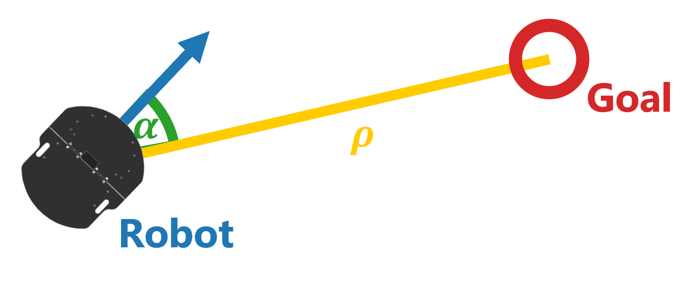
Take as a simple example a mobile robot witch is tasked to reach a goal on a plane without any obstacles.

Ideally we want the robot to turn in the direction of the goal and start driving once it starts to look roughly in the right direction. Given our current distance from the target \(\rho\) and our current orientation relative to the goal \(\alpha\), the control can be modeled as a simple circuit:

First the two sensory inputs are normalized and then combined using an AND gate. Since the output of the circuit is also normalized it has to be rescaled to the maximum angular and linear velocity. This is the general workflow of direct behavior circuit based control, normalize the circuit input, combine the inputs based on logic based rules and then rescale the output.
Note that while the distance to the target is always positive the angle \(\alpha\) cam be both negative and positive. Moreover the output of the circuit should also be able to handle positive and negative values, because the robot needs to be able to turn right and left aswell as drive both forward and backwards.
This requires a new definition of the AND and OR gate defined on [-1,1], which we call Analogical Gates. The mathematical derivation of these analogical gates can be found here. More important for the purposes of understanding how to use these gates is how to interpret negative and positive values. In the case of binary gates 1 can be thought of as true and 0 can be thought of as false. The new interpretation of positive and negative values is already described in the previous paragraph. If a command of 1 can be though of as driving to the right, a command of -1 can be though of as driving to the left. Thus one can intepret -1 as the opposite action of 1 while 0 means no action at all.
It can be a bit difficult at first to work with these analogical gates, which is why the section about circuit design will offer guidelines and examples of more complex circuit capable of avoiding obstacles, navigating mazes and more.